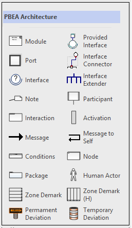
Visio Stencils (shapes and stereotypes) for the Principle Based Enterprise Architecture (PBEA) Architecture Diagramming style
Logical (Functional) Architecture shapes and stereotypes
The Visio shapes and stereotypes available from this site have been specifically developed to support the PBEA Architecture Diagramming style. This style is an extension of the "UML 2.0 specification from the OMG. The PBEA diagramming style guide for logical architecture is under construction.
Stencils
There are two stencils, one for shapes and one that just has the stereotypes. In general, the stereotype stencil is not needed since these are all part-of the module shape already

| Symbol Name | Illustration | Description |
| Shapes for System Views | ||
| Module |  |
Used for either a Module or Multi-Module. Right click on the shape to access the context menu to set
|
| Port |  |
Denotes the port via which Interface are exposed from modules. Ports may be named (press F2 to enter text). Text may be positioned via the control (yellow pin). There are two sizes (small, large) that have no prescribed meaning other than for aesthetics. |
| Interface |  |
A ball and socket to be used between ports (on modules) representing an Interface contract. Right click on the shape to access the context menu to set:
|
| Provided Interface |  |
A combination of a port, an interface ball-and-socket and a dynamic connector on the provider side. The shape automatically orients itself when attached to the side of a module shape. The consumer-side (the socket) can be connected to any module that calls the provider. |
| Note |  |
Attach to Interfaces to add data model definition. Attach to anything else to add additional descriptive info. Visio comes with a ton of other notes / callouts that are just as good if not better than this one. |
| Temporary Deviation |  |
Indicates a deviation that is intended to be revised in order to adhere to architectural standards in the component’s near-term future. |
| Permanent Deviation |  |
Indicates a component deviation that is expected to persist for the duration of that component’s existence. |
| Shapes for Sequence Diagrams | ||
| Interaction |  |
The Interaction shape represents a number of different elements in the Sequence diagram all with a single shape including:
|
| Participant |  |
Denotes the module responsible for the actions performed on its lifeline (the dotted line hanging down). These are placed along the top of the Interaction shape in the sequence diagram.(usually in a single row). |
| Activation |  |
Illustrates the duration of the participant's activation / lifespan along the lifeline as it reacts to messages. |
| Message |  |
Multiple message types between activation areas of Participants. The right click menu allows selection between:
|
| Message to self |  |
Denotes a call to the same object instance (generally used to show modularization in large processes). |
| Shapes for Deployment Diagrams | ||
| Zone Demarcation |  |
The Zone Demarcation shape is used as the Deployment skeleton or in system views where zone demarcation is necessary. There is a yellow control along the bottom edge allowing up to six zones to be defined. Click one of the zone separators until it alone is selected and press F2 to change the zone text (displayed along the right edge) |
| Node | 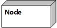 |
Illustrates a compute or storage instance (may be physical or virtual). Press F2 to set the Node Name. Right Click to Configure the Node. |
| Firewall |  |
Use this stereotype at the appropriate zone demarcations to show which logical boundaries are also physical boundaries |
Terms of Use
These shapes are copyright Principle Based Enterprise Architecture (PBEA) and iankoenig.com. They are provided AS-IS and free of charge. There are no express or implied warranties. Updates and bug fixes will be made as and when deemed appropriate by the author, with no guarantees expressed or implied. You are free to use the shapes, modify them and redistribute them as you wish. If you do redistribute the shapes we'd appreciate an acknowledgement via web link back to this page, but that is not mandatory. If you do make any interesting changes, we'd appreciate knowing but that is not mandatory either. Please do not remove the original copyright. By virtue of downloading the shapes you agree to these terms.
How to Download the Shapes
For each shape stencil (below), click the link and select "Save" (not "Open"). Next unzip the stencil files (.vss for Visio 2010- and .vssx for Visio 2013+) and save to your "My Shapes" Directory, which Visio normally places in the Documents folder.
Shape stencils for Visio 2003 - 2010
Zip file containing shape and stereotype stencilsShape stencils for Visio 2013+
Zip file containing shape and stereotype stencilsGetting Help
If you need help, please send an email to the contact email address in the left navigation bar. Emails will be prioritized and responded to as time allows.